The Embedded Super PLCs -
TRiLOGI 4.13 - The User-Friendly Ladder + TBASIC Editor and Simulator
Click Here for FREE Downloading of TRiLOGI (Evaluation) Software
1. Insert Element
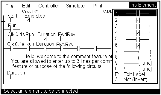
To add an element to the ladder diagram, you simply press the <Ins> key and pick an item from the Insert Element pull down menu as shown above. This menu lets you create Normally-Open (NO) or Normally-Closed (NC) contacts in series or in parallel. One or more coils can be connected by choosing Item "7" or "8". To insert a special function, select Item "9" or "0" (for multiple function) and the special function menu will appear as described in the next section.
2. Special Functions
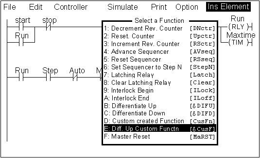
- [DNctr],[Upctr],[RSctr] - Reversible up/down ring counter functions.
- [AVseq],[RSseq],[StepN] - You can advance any one of the 8 sequencers one step at a time or even randomly set the step counter of any sequencer to any integer value between 0 and 31.
- [Latch],[Clear] - When activated, the associated output or internal relay will remain ON until it is reset by the [Clear] function acted on the same output or relay.
- [Ilock],[ILoff] - This is equivalent to a master relay with sub-branches.
- [DIFU],[DIFD] --The associated relay will turn on for one scan time when its execution condition goes from OFF to ON or ON to OFF.
- [CusFn] - Execute the Custom Function (1-128) written in TBASIC.
- [CusF] - Execute the Custom Function (1-128) for one scan time when the execution condition goes from OFF to ON.
3. Special Bits
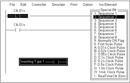
- Sequencer 1 to 8. T100MX supports 8 sequencers with 32 steps each (Step #0 to Step #31).. Each step of the sequencer can be used as a contact in the ladder diagram. E.g. Seq1:5 represents Step #5 , which means that the contact with the name "Seq1:5" will be turned ON when the step counter of the sequencer reaches the value of '5' and will be OFF when the step counter is at any other value.
- Clock Pulses - Eight clock pulses with periods of 0.01s to 1 minute are available on the T100MX PLC. They can be used as a NO or NC contact in the ladder diagram.
- Real Time Clock Error - This flag is used as an indicator that the Real Timer Clock in the PLC has been reset to factory pre-set date and time due to power failure. This warns users that they must set the clock properly if time-scheduled events are required.
4. Edit Custom Function
The custom function editor window allows creation of up to 60 lines of TBASIC program statements. Each line can contain a maximum of 70 characters. The extreme left column of the editor window shows the line number from 1-60. In one screen only 20 lines are visible. You can however easily scroll up and down in pages using the <PgUp>, <PgDn> keys and the cursor keys.
5. Real Time Simulation
While constructing your ladder program you can simulate it using TRiLOGI's unique real-time Simulator. When you invoke the Simulator, you will see a screen of I/Os organized into 7 columns:
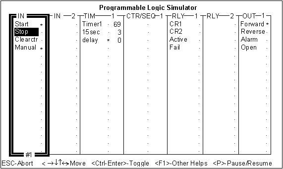
The first two columns show Inputs, followed by Timers, Counters/Sequencers, Internal Relays and Outputs. Beside each I/O, an indicator lamp indicates whether the I/O is ON or OFF. You can move the highlight bar to any I/O and press the <Enter> key to toggle its status and the status of all the other I/Os will be immediately updated according to the ladder program. A red "*" symbol means an I/O is ON whereas a grey "." means it is OFF.
In addition, you can view the values of all variables used by TBASIC on the “View Variables” window during simulation:
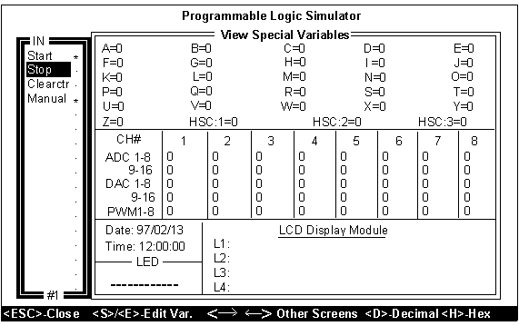
All 32-bit integer A to Z, A/D, D/A, PWM and Real Time Clock values are grouped into one screen. By pressing the and keys you can scroll to the String Variable screen to display A$ to Z$ and Data Memory screen to display DM[1] to DM[4000].
6. On-Line Monitoring and Control
TRiLOGI can watch in real time the status of all the I/Os, timers, counters and the values of all internal variables within the PLC, It also permits you to pause the PLC and remotely forced-set or reset any I/Os or modify the current value of the timers, counters and any variables.
The I/Os and variables can be monitored on a full screen display similar to the Simulator-screen, and the I/Os status can also be monitored directly on the ladder diagram. This feature helps greatly during debugging and fine-tuning of your PLC program.
7. TBASIC Components: Statements, Functions and Operators
©
Copyright 2001 Triangle Research International, Inc
All Rights Reserved

