E10-Relay+ Self Diagnostic Procedure

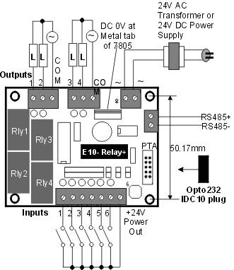
1) Connect AC 24V or DC 24V power to to the E10-Relay+ PLC's power supply terminal.  Turn on power to the power supply. The green power LED on the PLC should light up. Use a voltmeter to verify that valid AC or DC voltage is available at the power supply screw terminal.
2) If smoke or burning smell appears when the power supply is turned ON, then turn it OFF immediately. Most likely some components have short-circuited. Check for visual clue. The most likely component will be the 75HVD3082 RS485 driver or the ULN2003A relay driver.  Remove these component from their socket one at a time if you are not sure, then apply power to the PLC again. If there is no more smoke then you can confirm which part is short-circuit. You can purchase these part number from many electronic component supplier such as Digikey or Jameco or contact support@tri-plc.com to purchase the parts.


3)
Connect the IDC plug end of the Opto232 adapter to the E10-Relay+ PLC's 10-way IDC header, and the DB9 end of the Opto232 to the PC's serial port. Run WinTRiLOGI version 3.5. Click "Controller" and select "Serial Port Setup". Check to ensure that the correct COM port is selected and that the baud rate is 9600, 8 data bits, 1 stop bit and None for parity, 'Time out' is 500ms. If you need to make any changes, click on the "Close Port" button first.

At the "Command String" text field, enter  "IR*" and press <Enter>". If the PLC returns a response string "IRnn*" (where nn is a hexadecimal number between 00 and FF, the default is "IR01*") then you have successfully established communication with the PLC. If there is no response from PLC, click on the "Close Port" button, and select another COM port from the "Port Name" choice box and try again.

Note: If you receive a response string  "IR*" (without the ID) then the COM port is not a valid COM port (most likely it is a modem port) and what you receive is merely an echo of the command you sent to the COM port. It is not a response from the PLC

wtl3sersetup1.jpg (21024 bytes)
4) If you receive no response from the PLC, then it is either :
  1. The PLC's CPU is bad.
  2. The Opto232 adapter is bad (rarely happen).
  3. The PC's COM port is bad. You can test whether the PC's COM port is working by testing the COM port with other devices, or change a PC and try the same test mentioned above.

If the PC COM port is good but you still can't get communication with the PLC, then you may want to contact info@tri-plc.com to request for an RMA number and send the PLC for service repair.

5) If communication is OK, then you can transfer the program "e10test.pe3" (a copy is available at: http://www.tri-plc.com/selftest/plctestprograms.zip ) to the E10-Relay+ PLC. The 4 output LEDs should be blinking once every second after the program has been transferred to the PLC. You can also hear clicking sound from the 4 output relays when the electromagnetic close and open the contacts. Use an Ohmeter to check for continuity in the relay contact whenever it closes. Verify that all four relays make and break their contact every second. If any relay is bad they should be replaced.   The relay part number is JQ1A-24V and made by NAIS (aka Pansonic or Matsushita Electric) and is available from TRi or other electronic component suppliers.
6)
Connect one end of a wire to the +24V terminal to the right of input #6 screw terminal, and use the other end of the wire as probe and touch the screw terminal of input #1 to  #6. The corresponding output #1-4 will be turned ON immediately in respond to input #1-4 and you should hear the relay clicking sound.  Input #5 will turn ON output #1 and input #6 will turn ON output #2.

If all outputs respond properly to the activation of their corresponding inputs, then the PLC has passed all I/O tests and has no problems.

e10npnsetup.jpg (27884 bytes)