T100MD-1616+ Self Diagnostic Procedure
Next, connect 24VDC power supply to to the T100MD1616+ PLC. Make sure that the power supply polarity is correct before turning on power. Turn on the power supply. The green power LED on the PLC should light up. Use a voltmeter to verify that valid DC voltage is available at the power supply screw terminal. Note that T100MD1616+ may also be powered by 12VDC power supply, but you should short jumper J1 (which is next to power supply LED) using the provided jumper block when connecting 12V to the PLC.
If the T100MD1616+ CPU is alive and the output circuit are working, then you should see the three status LEDs (green RTCError, red Pause, red RunError) light up for between 1 and 3 seconds (depending on the length of program residing in the PLC) and then the Pause and RunError LED should go off. RTCError LED will remain lighted if there is no MX-RTC installed. This indicates that the CPU has successfully loaded the program from the EEPROM and the program will run immediately.
If the status LED did not light up, or they do not turn off after lighting up, and you have verified that the power supply voltage is correct, then there is some serious problem with the PLC which may involve more than one IC. You should contact support@tri-plc.com and request for an RMA # and RMA procedure to send the PLC to our service center for service and repair.
| If smoke or burning smell appears after the power supply is
turned ON, then turn it OFF immediately. Most likely it is either the power supply has
been connected in reverse polarity, or the output driver ULN2803A (for output #5 to
#8) is damaged due to overload. Check for visual clue. Remove ULN2803A output driver from
its socket if you are not sure, then apply power to the PLC again. If there is no more
smoke then it is most likely a shorted ULN2803A. You can purchase this part number easily
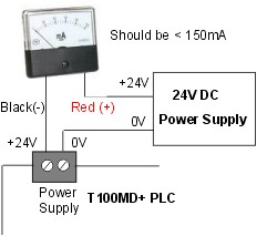
from many electronic component supplier such as Digikey or Jameco or contact support@tri-plc.com to purchase the part. If the PLC status LED lights up and goes off as described above, and the power supply is steady, you may like to check the power supply current to the PLC using a mA meter by connecting the meter in series between the +24V power supply and the PLC's positive power terminal. If the supply current exceeds 150mA while all outputs are OFF then there is likely to be some damaged components on the PLC. You should contact support@tri-plc.com and request for an RMA # and RMA procedure to send the PLC to our service center for service and repair.
|
|
| Connect the male end of the DB9 cable to T100MD1616+ PLC's
RS232 port (COMM1), and the female end of the DB9 cable to the PC's serial port. Run
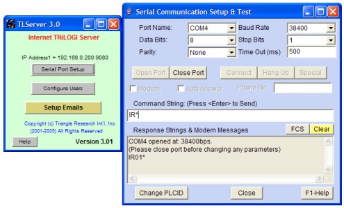
TLServer version 2.x or 3.x. Click "Serial Port Setup" on TLServer front panel.
Check to ensure that the correct COM port is selected and that the baud rate is 38,400, 8
data bits, 1 stop bit and None for parity, 'Time out' is 500ms. If you need to make any
changes, click on the "Close Port" button first. At the "Command String" text field, enter "IR*" and press <Enter>". If the PLC returns a response string "IRnn*" (where nn is a hexadecimal number between 00 and FF, the default is "IR01*") then you have successfully established communication with the PLC. If there is no response from PLC, click on the "Close Port" button, and select another COM port from the "Port Name" choice box and try again.
|
 |
- The PLC program has altered the COMM1 port setting or the PLC program is writing out of the COMM1 port and therefore interfering with the host link command that TLServer try to send to it.
- The PLC's COMM1 port is bad.
- The PC's COM port is bad. You can test whether the PC's COM port is working by testing the COM port with other devices, or change a PC and try the same test mentioned above.
Quite frequently the problem is due to (a) which happens that the previous program loaded into the PLC has somehow altered the COMM1 port setting or disable it altogether when the program run. You can recover the PLC by turning ON DIP switch #4 to ON, then power cycle the PLC. You will see that the red "Pause" status LED will remain lit after the CPU has loaded its program from the EEPROM. DIP Switch #4 halts the CPU and prevent it from executing any PLC program so that the COMM1 port settings will not be changed by the program.
When a T100MD+ PLC is power-ON RESET with DIP switch #4 on, the CPU set the COMM1 port default baud rate to 9600 bps, 8 data bits, 1 stop bit and no parity. Hence you must click on the "Close Port" button on the "Serial Communication Setup & Test" window, change the baud rate to 9600 bps, and then re-try the "IR*" command to see if you can get a valid "IRnn*" response from the PLC. If you do get a valid response this time, then please use TRiLOGI to transfer a blank program to the PLC to overwrite the offending program. You would have recovered the PLC by now and you can then turn OFF DIP switch #4, power-cycle the PLC and then change the TLServer serial port back to 38,400 bps. You should now be able to send the "IR*" command and get a proper "IRnn*" response from the PLC.
If the above procedure is unsuccessful, then the PLC's COMM1 port may be damaged. You may want to contact info@tri-plc.com to request for an RMA if you prefer not to deal with desoldering/soldering of transistors. Otherwise, the two active components that control the T100MD1616+ PLC's COMM1 port are a PN2222 and a 2N4403 which are located just below the 74HC595 LCD driver IC. If you replace these two transistors the COMM1 port should be OK.
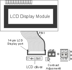
| Digital I/O Test Connect one end of a wire to the 0V terminal of the power supply and use the other end of the wire as a probe to touch the screw terminal of input #1 to #16. The corresponding output #1 to #16 will be turned ON immediately in response to input #1 to #16. If all outputs respond properly to the activation of their corresponding inputs, then the PLC has passed the digital I/O test. If an output LED does not light up when it is supposed to, then it could be a bad LED or a damaged output driver IC: TPIC6A595 (for output 1-4 and 9-16 as well as status LEDs) or ULN2803A (for output #5 to #8) . You can use a multi-meter's diode test range to probe on the two LED legs and see if it lights up. If the LED lights up when probed by the meter, but does not light up when the output is supposed to be turned ON, then most likely it is the damage to the output driver. You can purchase these IC from Digikey.com or contact support@tri-plc.com LCD port Test If a good LCD display was connected to the PLC, you should observe the message "Input 1-16 OK" on the second line of the LCD display when you have finished probing all 16 inputs. If a connected LCD shows nothing, it could be a bad LCD driver U5 (74HC595) that needs to be replaced. You may also want to turn the LCD constrast preset potentiometer (just below the RS485 terminal) to fully anti-clockwise (maximum constrast) in case it has be adjusted by someone else to see if the character shows up on the LCD display. The LCD display itself also could be damaged if you have previously plugged/unplugged the LCD connector without turning off the power to the PLC first. If the LCD display is damaged it is not repairable and need to be replaced with a new purchase. |
|
If you are using the MD-HMI, then you'll also need to test the PLC's expansion port. First, TURN OFF POWER to the PLC, then connect the the 10 way IDC cable from the MD-HMI to the PLC's expansion port. Turn ON power to the PLC and press the key 0 to 7 on the MD-HMI. The 8 signal LEDs on the MD-HMI should light up one at a time when the key is pressed. This indicates that the expansion port on the T100MD-1616+ PLC is functioning properly.
If you are using an Expansion board such as EXP1616R or EXP4040, then you can also use it to test the PLC's expansion port. First, TURN OFF POWER to the PLC, then connect the expansion board IDC connector to the PLC's expansion port. Turn ON power to the PLC and turn ON and OFF each digital input on the expansion board. The corresponding digital output should be turned ON and OFF immediately (i.e. input #17 controls output #17, input #24 controls output #24, and so on). This indicates that the expansion port on the T100MD-1616+ PLC is functioning properly.
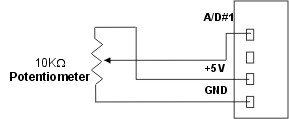
| Analog I/O Test T100MD1616+ requires a 12 to 24V DC power supply connected to its analog power supply section. You can use the same power supply as the PLC for powering the analog section. With the power to the PLC and analog section turned ON, use an accurate voltmeter to measure the voltage at the +5V DC out terminal with respect to 0V (AGND) of the analog power supply. You should get a 5.000V reading. Otherwise you can adjust the "Cal AVcc" preset pot below the DIP switches on the PLC to calibrate the PLC's analog reference voltage until you obtain a 5.000V reading. The "mdtest.pc5" program would have set the D/A #1 output to 2048, which means that if you use a milliamp meter to measure the D/A #1 terminal with respect to 0V you should get 10mA reading. You can adjust the Cal DA1 potentiometer to calibrate the D/A #1 output until it reads a 10.00 mA output. The "mdtest.pc5" program also reads the value of analog inputs 1-4 continuously. So you can use a potentiometer to apply a voltage between 0 and 1V to the analog input #1 & #2, or a voltage between 0 and 5V to analog input #3 & 4 , and you will be able to observe the analog input reading of between 0 to 4092 via the Online Monitoring -> View Variable screen. Note that analog inputs that are not connected to any voltage (i.e. floating) will not record zero reading, instead they tend to float around the reading of the adjacent pins and hence the readings are indeterminate for those disconnected analog inputs. If A/D #1 to #4 return correct readings and D/A #1 output the correct current, then the PLC has passed the analog I/O test. |

|
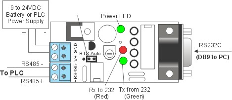
| RS485 Test To test the RS485 port, you'll need to connect the PC''s RS232 port to the DB9 side of the Auto485 adapter and also connect a 9 to 24V power supply to Auo485. Next, connect RS485 (+) terminal on the Auto485 to the PLC's RS485 (+) terminal and do the same for the RS485 (-) terminals. Next, use the TRiLOGI program to perform online monitoring of the PLC exactly the same way when the PC is connected to the PLC's RS232 port. If successful you will also see the green and red Tx and Rx LEDs on the Auto485 blinking rapidly as the PC communicates with the PLC via RS485. If the RS485 failed to work, then most likely it is the 8 pin RS485 driver "75HVD3082" that is damaged. Since this is a socketed IC you should be able to find a replacement from electronic component supplier such as Digikey or contact support@tri-plc.com to purchase the IC. (Note: an easier to find substitute part number is SN75176).
|
 |
If the T100MD1616+ PLC passed all the above functional tests, then it essentially has no problem and may be put to production use.
