Application Note: Interfacing to ICP-CON I-7000 Modules
Note: For short distance (less than 3 ft) and only a few ICP-7000 devices being used, the two 560W biasing resistors and the 120W termination resistor may be omitted.
The good news is, ICP-DAS, the manufacturer of I-7000 modules, has provided a free "I-7000 Utility Software" that can be downloaded from their website at:
http://www.icpdas.com/download/7000/7000.htm
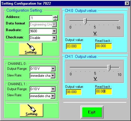
You should download "disk1.exe" and the rest of the ".cab" files into a temporary directory and run disk1.exe to unzip the rest of the setup files into the same directory. Then run the "Setup" program to setup the I-7000 Utility software. We tested this Utility software and found it to be much more convenient to use for configuring the I-7000 modules. A screen shot for the Utility software is as follow:
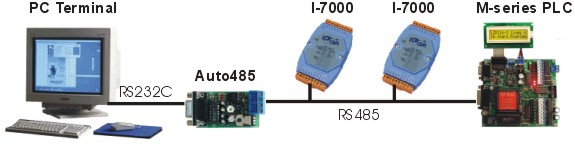
 Note that since most
PCs do not have built-in RS485 interface, you will need an auto-turnaround RS232 to
RS485 converter, such as the Auto485 to interface to the ICP-CON modules.
Should you face communication problem between the PLC and the I-7000 during testing, you
can also conveniently use the Auto485 and a HyperTerminal program to "spy" on
the RS485 communication lines and observe what is going on to find out who is not talking
correctly. This makes it a powerful yet low cost tool for trouble-shooting the
communication problem and is therefore highly recommended.
Note that since most
PCs do not have built-in RS485 interface, you will need an auto-turnaround RS232 to
RS485 converter, such as the Auto485 to interface to the ICP-CON modules.
Should you face communication problem between the PLC and the I-7000 during testing, you
can also conveniently use the Auto485 and a HyperTerminal program to "spy" on
the RS485 communication lines and observe what is going on to find out who is not talking
correctly. This makes it a powerful yet low cost tool for trouble-shooting the
communication problem and is therefore highly recommended.
The NETCMD$ was originally designed for a M-series PLC to talk to other slave M-series PLCs using the PLC’s native communication protocols. Normally the NETCMD$ command will compute the two-byte FCS characters and append to the end of the supplied command string x$ and is supposed to check the returned string for correct FCS before accepting the response string.
However, there is a special provision for NETCMD$ that enables it to be used for communicating using 3rd party ASCII protocol: i.e. by appending a "~" character to the end of the command string, the NETCMD$ will not append the FCS characters to the outgoing string. (Note that a NETCMD$ with a "~" suffix in the command string will not send out the CR character automatically, so you have to append the CR character using CHR$(13) to the command string before terminating it with a "~" character.)
NETCMD$ with a "~" suffix will also not check for FCS in the received string and it simply returns whatever CR-terminated response string it receive from the serial device such as the I-7000 to the caller.
Our tests show that this command works wonderfully well with the I-7000 and is used throughout the example programs for interfacing to the I-7000. Please download the sample trilogi program files that we used for testing from the following weblink:
http://www.tri-plc.com/trilogi/I-7000.zipThe model I-7017 is a 16-bit, 8-channel analog input module that can be configured to measure input range of ± 150mV, ± 500mV , ± 1V, ± 5V, ± 10V and ± 20mA. Please open the sample program "I-7017.PC5" and transfer it to your PLC for testing. The following paragraphs describe the operations carried out by each function. Initialization By default the device has the following configuration:
- ID
= 01RANGE = + 10VBAUDRATE : 9600 bps.UNIT : Engineering unit that directly represents the voltage in mV, V or current in mA.The command for changing the I-7017’s configuration is "%AANNTTCCFF". In our demo program ("I-7017.PC5"), we use a custom function #250 to change the configuration. The "InitICP" need to be turned on momentarily to trigger the Fn_#250 to initialize the I-7017. For diagnostic purpose the function #250 also reports the status of initialization on the LCD display.
To simplify testing, we keep the ID = 01 and the BAUDRATE= 9600 in the test program, but we change the RANGE to + 5V and the UNIT to percentage of full scale. You can modify the initialization string to change the RANGE easily. But if you want to change the UNIT then you will need to modify the Fn_#252 and Fn_#253 to handle the returned data, which may be of a different format.
Although the "InitICP" action can be removed from the program after the I-7017 has been initialized, we suggest keeping it so that in case you have to replace the I-7017 with a new unit it will be properly initialized to the format supported by the other functions.
Reading Single Channel
The contact: "RdSingleAD" is used to trigger the custom function 251 that will send out command to read a single channel of ADC data from I-7017. This may take up less communication time than to read all 8 analog inputs (to be discussed next) just in order to get an updated value of one channel of ADC.
Custom Function #251 is actually just a shell function that put the channel number (0 to 7) in the variable N, and then calls the Fn_#252 that does the actual job. The data read from the ADC channel will be returned in data memory DM[10] and Fn_#251 will display the data on the LCD display.
Note that since we have initialized the I-7017 to use the "% Span" as its UNIT, the data will be returned from the I=7017 as string "+xxx.xx" or "–xxx.xx". Hence 34.56% of full scale will be returned as +034.56. and –3.29% of full scale will be returned as "-003.29". Function #252 will extract the data from the returned string and convert them into integer value from –10000 to 10000. i.e. each digit represent 0.01%. In the above example, "+034.56" will be converted to 3456 and "–003.29" will be converted to –329. The converted data is stored in DM[1].
Reading All 8 Analog Inputs
If you want to continuously monitor the readings of a few channels of ADCs, then it may be more economical in terms of communication overhead to use the "#AA" command to read all 8 channels of the ADC data in a single exchange. The custom function #253 uses this command to read the data of all the ADC channels and return them in the data memory DM[11] to DM[18]. The captured data are displayed on the 4x20 LCD display for diagnostic purpose. If you connect a parallel clock pulse to the "RdAllADC" contact then the Fn_#253 will be called repeatedly and you can observe the changes on the LCD display.
Please note that if you leave any of the ADC channel unconnected (floating) it has a tendency to float to the value closed to its neighboring channel. Hence if you connect say a +2V to AD0, you will observe that any unconnected AD #1,2,….will all be reporting readings that are quite close to AD0. You need not be alarmed by it. As soon as you connect the floating A/D inputs to some load or active voltage level they will report the correct readings.
Changing the BAUD RATE
For two devices to communicate properly via their serial ports, they must use the same baud rate and communication format. The default baud rate for M-series PLC’s RS485 port is 38,400, whereas that on the I-7017 is 9600 bps. You can either change the PLC baud rate down or the I-7017’s baud rate up to the same settings. To make it simpler we use the TBASIC SETBAUD command to change the PLC baud rate to 9600 to match that of the I-7017 so that you don’t have to change the I-7017 default baud rate. However, you can also elect to change the I-7017 baud rate to 38400bps instead so that they can communicate at a higher baud rate. I-7017 has a requirement that its "INIT*" pin must be grounded before the baud rate can be changed. Please refer to the I-7017 manual for details. If you have changed the I-7017 baud rate that then the SETBAUD command can either be removed or changed to SETBAUD 3,6 to set it to 38,400 bps again.The model I-7022 is a 12-bit, 2-channel analog output module that can be configured to output 0-10V, 0-20mA or 4-20mA current. Each channel has its own separate voltage and current terminals (the voltage and current channel are internally related by the formula V = I (mA) x 0.5). Each channel can be independently configured for different output settings. You can also program the output to rise and fall in a ramp instead of changing instantly and the "slew rate" of each channel can be independently programmed.Please open the sample program "I-7022.PC5" and transfer it to your PLC for testing. The following paragraphs describe the operations carried out by each function.
Initialization
By default the device has the following configuration:
- ID
= 01RANGE = + 10VBAUDRATE : 9600 bps.UNIT : Engineering unit that directly represents the voltage in mV, V or current in mA.The command for changing the I-7022’s configuration is "%AANNTTCCFF", where "AA" is the ID. In our demo program ("I-7022.PC5"), we use a custom function #240 to change the configuration. The "InitICP" need to be turned on momentarily to trigger the Fn_#240 to initialize the I-7022. For diagnostic purpose the function #250 also reports the status of initialization on the LCD display.
To simplify testing, we keep the ID = 01 and the BAUDRATE= 9600 in the test program, but we changed the UNIT to "% of Span" which means the PLC has to supply data to the I-7022 as strings in the format of "+xxx.xx". (from "000.00" to "100.00").
Note that the type "TT" for model I-7022 must be set to "3F" only. This is because I-7022 offers another command: "$AA9NTS" for independently setting the output type and slew rates for each channel. If you put any other values than "3F" in the "TT" the I-7022 will reject the command with a invalid response "?AA".
In our sample program, we use the "$AA9NTS" to set the two analog output channels DA0 and DA1 to the following settings:
- DA0 : 0-20mA, immediate change.
- DA1 : 4-20mA, slew rate = 1mA/second.
The slew rate setting for DA1 means that the DA1 output will not jump immediately to a new set value, but will follow a linear ramp-up or ramp-down over time. E.g. It will take 16 seconds to go from 4 mA to 20mA. This can be observed using a multi-meter or an oscilloscope.
Writing to Analog Outputs (DA0 and DA1)
The command used for writing data to the DA outputs is "#AANxxx.xx" where "AA" is the ID, "N" is the channel and "xxx.xx" is the string of data representing the range.This command is the only one used by the Fn_#241 to send the data to the I-7022. To use this function, the channel number is passed in the variable N and the output data is passed in the variable X. The output data is to be represented as integer where each unit represent 0.01% of full scale. Fn_#252 converts the integer number in X into "xxx.xx" format and send it to I-7022 using the NETCMD$ command.
In our sample program "I-7022.PC5" we defined 2 input buttons to set the DA0 and DA1 and a 3rd input button to reset both DA0 and DA1 to zero output.
You should connect a multi-meter to the corresponding output channel and triggered the "WriteDA0" and "WriteDA1" contacts to set the value to each output. For DA0 we have defined it to be 0-20mA, so if X = 0, the current output is 0mA and the voltage output is 0V. The moment you trigger the "WriteDA0" contact, X = 5000 which means DA0 is set to 50.00% of full scale, so the current output for DA0 should immediately jump to 10mA and the voltage output will jump to 5V.
Since DA1 is defined as 4-20mA at a slew rate of 1mA/second, when X = 0, the current output will show 4mA which is the minimum value, and the voltage output for this DA will show 2V. When you trigger the "WriteDA1", X = 7500 which means DA1 is set to 75.00% of full scale, you should observe that the output will rise slowly from 4mA to 16mA. It will take 12 seconds to complete the ramp up since the slew rate is 1mA per second. The voltage output will also rise at the same ramp rate from 2V to 8V.